Well after many weeks of waiting for all the parts to arrive from various places in the world, I have just about everything I needed to get started. So this weekend I set up shop in the guest room (temporarily because mom is recarpetting). 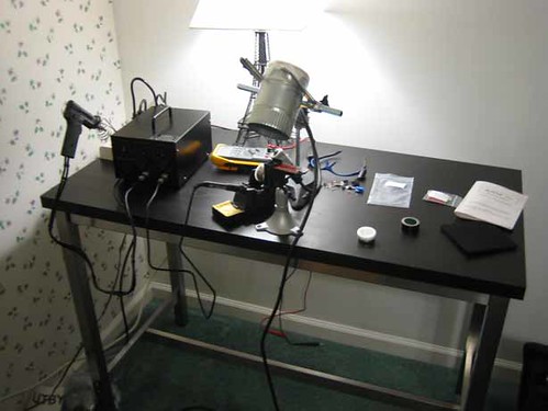
I set up my new soldering station - complete with delsoldering gun, got to try out my breadboard vices, and utilized my DIY solder fume filter! The eifel tower lamp is just for some extra light, or should I say...lumière!
It’s a good thing that DIY projects aren’t an all or nothing thing. What I mean is that, I can choose to build my RepRap in steps. I don’t have to choose to spend $5k on a product that might not end up worth being $5k of awesomeness. Even if this project ends up costing $1000, I can choose to build it, or more importantly, buy it in steps. So think about all the parts that go into building something like this. There’s the frame, the hardware (motors, and nozzles and stuff), and the electronics. Well, if I can’t get the electronics working, there’s no point in building a frame or buying expensive motors. So there’s my starting point. And luckily, electronics are relatively inexpensive.
The Brain and How it Works
I love microcontrollers. I do, it’s just one of those things that I excel at, and I understand, and will probably make a career out of. Computers are cool, sure, but my brain wants to know how everything works. Why does a computer take so long to start up? How can it display something that I type and you’re now reading? How can a machine “think?” Knowing the basics of microcontrollers gave me the knowledge, or at least the basis to answer some of these ethereal questions. But it’s beyond the scope of this blog to talk about the inner workings of a microcontroller (and I’m restraining myself because I want to spew out information about the ALU, bits and bytes).
While in college I worked primarily with the Motorola HC6811 microcontroller. We had 30 development boards, and the course I was taught in “Microcomputer Engineering” was based on these boards. A development board is an electronics board that has LEDs, speakers, LCD’s, and Input/Output terminals that are all hooked up to the microcontroller. When connected to a computer, the microcontroller can be programmed to control the different peripherals to make sure that everything is working. I programmed the HC6811 with very low level code. Let’s say that you wanted to get the HC6811 to add 1 + 2. I would type in a program to control the HC6811’s registers with easy to remember mnemonics. These mnemonics would be translated by the program I was writing it in (THRSim) to Op Codes, which would be sent (via serial cable) to the microcontroller where it would understand what to do in binary code (1’s and 0’s).
Mnemonic Code (What I wrote):
LDAA #$01
ADDA #$02
OP Code (Translation):
86 (LDAA)
01
8B (ADDA)
02
Binary Code (What the HC6811 Understands):
1000 0110 (86)
0000 0001 (01)
1000 1011 (8B)
0000 0010 (02)
The above code sections are equivalent. The Mnemonic code is easy for a human to remember, but cannot be understood by the microcontroller. This was often a very tedious and cumbersome process. Though I LOVE writing in Mnemonics (because it’s so cool to manipulate and understand exactly how your computer is working) I was having to worry about how to have the microcontroller do things, instead of what I wanted it to do. It’s quite literally micromanaging (pardon the pun) the computer. Early on, engineers decided the best ways for how the microcontroller should do simple things like adding, and standardized the way things should be done. They put this efficiency into a translator known as a compiler so that engineers and programmers could focus on the “what” instead of the “how.” This is what we now call high level language (C, C++, Java…). So now I can control my computer with a language that looks strikingly similar to English, and not have to worry about low level concepts like how many accumulators does the microcontroller have, and what are the general purpose ones?
Now I can write this:
int a = 1;
int b = 2;
int c = a + b;
Unfortunately for me, a high level language compiler hadn’t been written for my precious HC6811, so in college I had to stick with the basics (literally).
Enter the Arduino
The Arduino is the name of a line of development boards based on the Atmel Atmega microcontrollers. It has several different “flavors” based on the users needs, but I’ve found that most of the different microcontroller boards out there are differentiated by their number of I/O ports. Lets say that Microcontroller A had one I/O port available. This usually means that there are only 8 Input/Output lines for use. So if one wanted to control 9 LEDS, well you couldn’t (at least independently) do it. The Arduino uses free software to program it in a C-like higher level language. It is geared for DIYers.
| Sanguino | Arduino | |
| Processor | ||
| GPIO Pins | 32 | 20 |
| Analog Pins | 8 | 6 |
| PWM Pins | 6 | 6 |
| Flash Memory | 64K | 16K |
| RAM | 4096 bytes | 1024 bytes |
| EEPROM | 2048 bytes | 512 bytes |
| External Interrupts | 3 | 2 |
| JTAG | yes | no |
| I2C | yes | yes |
| SPI | yes | yes |
| USARTs | 2 | 1 |
| Onboard USB<->Serial Converter? | no | yes |
| Breadboard compatible | yes | sort of1 |
| Made by |
All you really need to take from the above table, is that it has moar stuf! It’s also compatable with the Arduino software, and designed by a fellow RepRapper Zach Hoeken. So this is what I went with. I bought the kit from www.wulfden.org along with the P4B serial adapter to connect the Sanguino to my computer (to program it).
Sanguino - $27
P4B Adapter - $5
Shipping - $5
Putting it Together
When I received the kit it came in a little baggie with all the necessary components ready to be soldered. 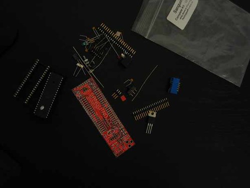
I matched up the components with their holes and soldered away! 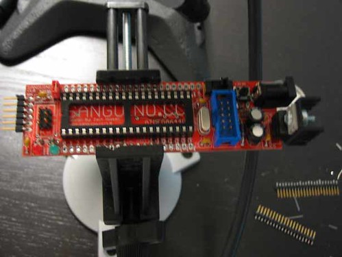
I had a problem with the headers. (The pins in the lower right hand corner). I originally soldered them upside down thinking that something would go on top of the board like a shield (an addon for Ethernet or something). I found out later that the pins needed to be soldered on the bottom so that I could put it into a breadboard. Duh! The desoldering took quite a bit of time, skill (that I didn’t have), and force (that I had way too much of). So now I’m waiting for my digikey order of replacement headers. /bonk
But once it was all in place, I found a plug that used to belong to a set of speakers and plugged it in. It worked as seen in the video below.

Connecting it to the Compy
The P4B serial adapter board took less time to solder because it was smaller. 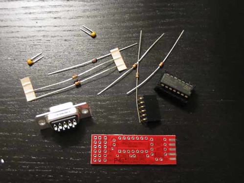
In the end, it looked great without any mistakes! 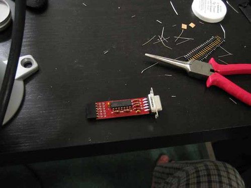
When I was done, I hooked it up to my Sarduino, and my USB>Serial cord up to it. I downloaded the Arduino software, and typed my first program.
void Setup()
{
pinMode(0,OUTPUT);
}
void Loop()
{
int a = digitalRead(0);
digitalWrite(0, !a);
delay(2000);
}
After a bit of debugging (I forgot the () after Setup and Loop) I clicked on upload, and the results are in the video below!

What Next
I need to solder on the headers (that I hope to get in the next few days) to the board so I can do some prototyping. Then I need to program the Sarduino to control a stepper motor (my heart be still). Stay tuned!
Reference
No comments:
Post a Comment
Note: Only a member of this blog may post a comment.